Forced ventilation airflow calculation according to IEC 61439-2
Verification of the temperature-rise of an assembly with active cooling (e.g., forced cooling, internal air conditioning, heat exchanger, etc.) and a total supply current not exceeding 1 600 A may be made by calculation.
Calculation procedure
1)
Calculate the permissible air temperature-rise inside the assembly by subtracting the maximum ambient air temperature outside the assembly from the lowest permissible maximum operating air temperature of all devices and components installed in the assembly as declared by the device manufacturer.
2)
Determine the total effective power loss as explained in 10.10.4.1 of IEC 61439-1:2020. The effective power losses of all circuits including interconnecting conductors shall be calculated assuming the circuits are operating at their group rated current.
3)
Calculate the maximum power loss the assembly enclosure can dissipate without ventilation and active cooling by using the method given in IEC TR 60890 or the enclosure manufacturer’s declared power dissipation data.
4)
Determine the power to be dissipated by active cooling by subtracting the maximum power loss the enclosure can dissipate without ventilation and active cooling from the total effective power loss.
5)
From the cooling equipment manufacturer’s data, determine the cooling equipment required (e.g., a fan) to ensure that the power to be dissipated by the active cooling can be removed by the active cooling without the air temperature-rise inside the enclosure exceeding the permissible maximum value.
Forced ventilation airflow calculation
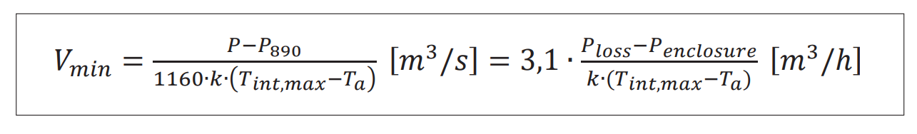
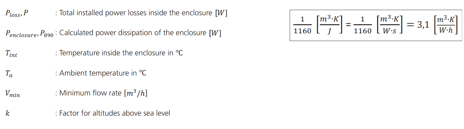
Table-1: Factor k for altitudes above sea level
Height (m)
| 0
| 500
| 1000
| 1500
| 2000
| 2500
| 3000
|
k
| 1.00
| 0.95
| 0.89
| 0.84
| 0.80
| 0.75
| 0.71
|
From calculated airflow rate to fan airflow rate selection
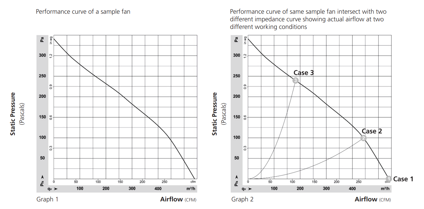
It is essential to take care how to select the correct fan. In general fans are usually described by two different properties. The first- one is its performance in case of free air flow, and the second-one is given in case of working against a load, for example, a grille or a filter. This second value, which is the lower one, shall be used to select the correct fan.
Care must be taken that there is no horizontal partition or other obstruction in the assembly or a section of an assembly that restricts the air flow. To avoid hot spots, adequate air circulation of the active components must be ensured in the assembly.
Sample performance curve of a imaginary fan with filter;
Point 1 - Sample 540 m3/h rated fan has a performance curve that intersect with horizontal airflow axe at 540 m3/h where static pressure is zero, which means air is flowing without resistance.
Point 2 - This fan is placed in a fan unit and mounted on top of a fully equipped assembly; which means air is flowing with resistance at 445 m3/h
Point 3 - After 6 months the airflow rate of this fan unit with filter (if it’s filter mat is not kept clean) is reduced to 180 m3/h
Case
| Status
| Fan Flow Rate (m3/h)
|
1
| Only fan is operating. There is no obstacle or resistance.
| 540
|
2
| The situation after devices are placed in the enclosure.
| 445
|
3
| Situation after filters are installed.
| 180
|
Use of forced ventilation requires maintenance to ensure consistent performance during the whole life of the assembly. Fan with filter units are ideal for dissipating heat loads cost effectively. The prerequisite is that the ambient air must be relatively clean.
Otherwise, filters are filled with contamination very quickly. Filter mats must be cleaned and/or replaced regularly.
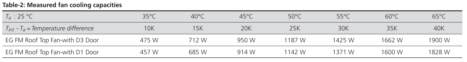
Measured cooling capacities
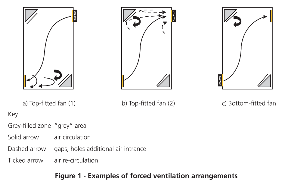
Installation considerations
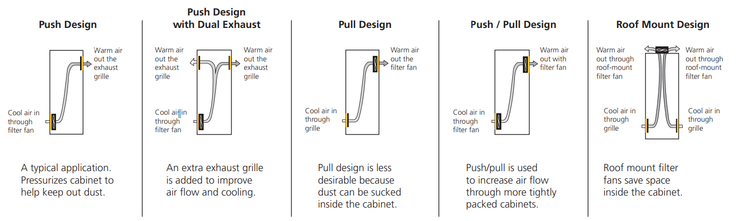
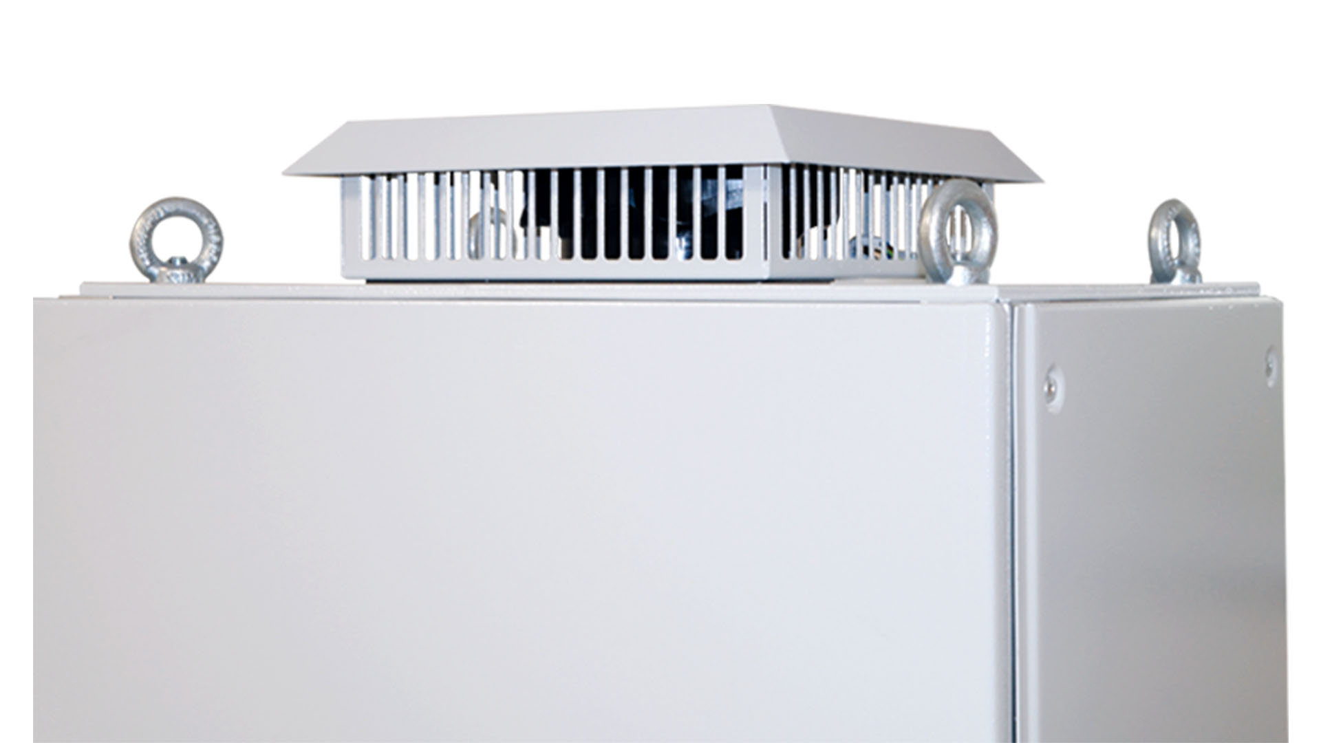
Filter fans are typically installed using a “Push Design”
Designers of assemblies using forced ventilation need to recognize there can be ‘grey areas’ within the assembly where the airflow is adversely affected by the forced cooling. The installation of temperature-critical devices within these spaces shall be avoided (see Figure 1a)). The place of installation and the direction of the air flow, e.g., pushing air into or sucking air out of the enclosure, can lead to different results. In case of installing the fan at the top of the
enclosure, to blow air out (see Figure 1b)), because the enclosures are usually not completely air-tight gaps, or some small holes can modify the air-forced circulation. This effect may reduce the cooling in some areas of the enclosure (see Figure 1b)). Another known consequence is that some polluted (unfiltered) air is drawn into the enclosure through these gaps. Based on those facts, the pushed-in air flow design with the fan placed at the bottom of the enclosure is the preferable solution in many cases (See Figure 1c).
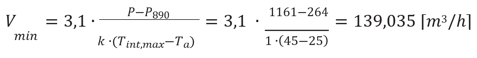
Fan
airflow calculation example
Total effective power loss (P)
: 1161 [W]
Enclosure dimensions (HxWxD)
: 2000x800x500 mm
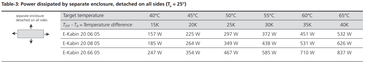
Type of installation of enclosure
: Separate enclosure, detached on all sides Tint : 45 °C ; Ta : 25 °C ; P890 : 264 [W] (From Table-3); Altitude : 100 [m]
Calculation of minimum flow rate of the fan:
Important Note
The integrated cooling fans positioned within the assembly of equipment such as motor drivers and power supplies can help ensure a homogeneous temperature distribution. However, these fans have a limited effect on removing heat from the assembly. In such cases, additional measures (such as a roof fan and filter unit) should be considered to prevent excessive temperature increase.

.jpg)
.jpg)


_shutterstock_750265378.webp)


.jpg)
.jpg)

.webp)
.jpg)
.jpg)
.png)
.jpg)
-(1)-(1).jpg)
-(1).jpg)
-(1).jpg)


.jpg)
.jpg)