Earthing
Main function of an electrical enclosure is to ensure the safety of operator and equipment. Appropriate precautions must be taken for the safety of personnel, property and electrical equipment located inside enclosures. Even careful design of switching systems and expert planning cannot prevent unwanted short-circuits when operating electrical systems. These must therefore be equipped with appropriate short circuit provisions. They must be able to conduct short-circuit currents without impairing safety.
Earthing connections are additional path for electrical current to return safely to the ground without danger to anyone in the event of a short circuit. If a short circuit did occur, the current would flow through the earthing connection. Causing a fuse blow or a circuit breaker trip is much preferable than the fatal shock that could result if the current was not grounded.
Earthing
The following standards should be considered regarding earthing:
• EN 62208:2011
Empty enclosures for low-voltage switchgear and control gear assemblies – General requirement
• EN 61439-1:2011
Low-voltage switchgear and control gear assemblies - Part 1: General rules
• EN 60204-1:2016
Safety of machinery - Electrical equipment of machines - Part 1: General requirements
Test method to verify earth continuity
It shall be verified that the different exposed conductive parts of the enclosure are effectively connected to the earthing terminal or contact of the protective circuit and that the resistance of the circuit does not exceed 0,1 Ω.
Verification shall be made using a resistance measuring instrument or arrangement which is capable of driving a current of at least 10 A (a.c. or d.c.). The current is passed between each exposed conductive part and the earthing termination point. The voltage drop between these points is measured. The resistance calculated from the current and this voltage drop shall not exceed 0,1 Ω.
Requirements for earth continuity providing protection against the consequences of faults within the enclosure
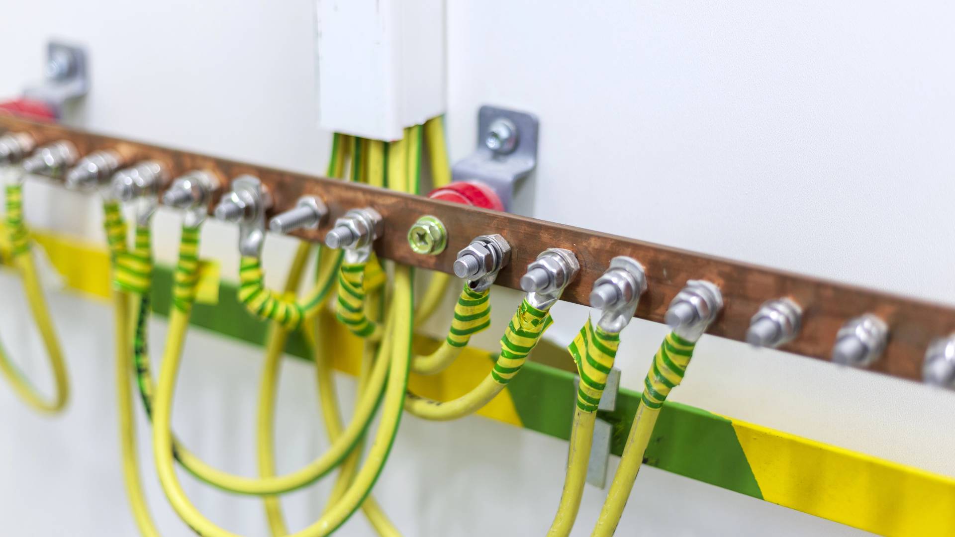
EAE enclosures have been designed to ensure earth continuity protection against the consequences of faults within the enclosure, so all exposed conductive parts are interconnected together and have low resistance to the earthing terminal. Thus, earthing terminal can be bonded via an earthing conductor to the earthing arrangement of the system. These interconnections may be achieved either by metal screwed connections, welding or other conductive connections or by a separate protective conductor.
For the continuity of these connections during operation or maintenance the following shall apply:
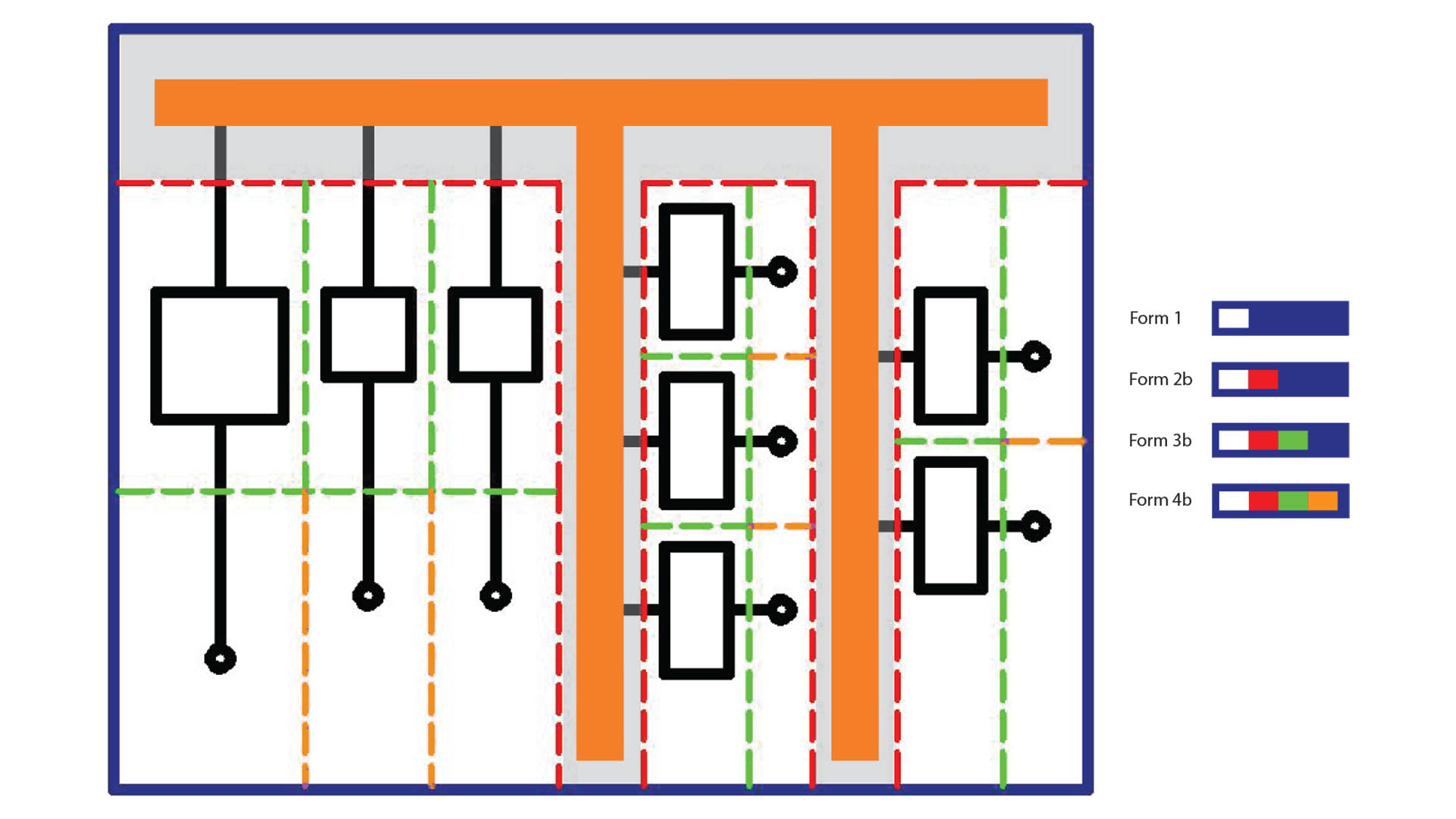
a) When a part of the enclosure is removed, for example for routine maintenance, the protective circuits (earth continuity) for the remainder of the enclosure shall not be interrupted.
b) For lids, doors, cover plates and the like, the usual metal screwed connections and metal hinges are considered sufficient to ensure continuity provided that no electrical equipment exceeding the limits of extra low voltage (ELV) (50 V AC or 120 V DC see: IEC 61140- 2016) is attached to them.
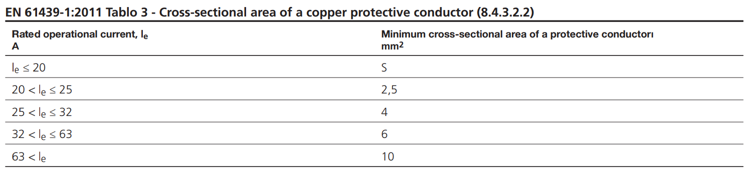
If apparatus with a voltage exceeding the limits of extra-low voltage are attached to lids, doors, or cover plates additional measures shall be taken to ensure earth continuity, therefore EAE accessories shall be mounted as protective conductors. These parts shall be fitted with a protective conductor (PE) whose cross-sectional area is in accordance with EN 61439-1:2011 Table 3 depending on the
highest rated operational current Ie of the apparatus attached, if the rated operational current of the attached apparatus is less than or equal to 16 A or an equivalent electrical connection especially designed and verified for this purpose (sliding contact, hinges protected against corrosion).
Exposed conductive parts of a device that cannot be connected to the protective circuit by the fixing means of the device shall be connected separately to the protective terminal of the enclosure by a conductor whose cross- sectional area is chosen according to EN 61439-1:2011 Table 3.
Current carrying capacity of the integrated contacting
The integrated contacting system of EAE enclosures ensure a conducting connection between all elements. The results of our tests and measurements confirm that the connections possess a contact resistance of less than 0.1 Ω, as demanded in EN 62208:2011.
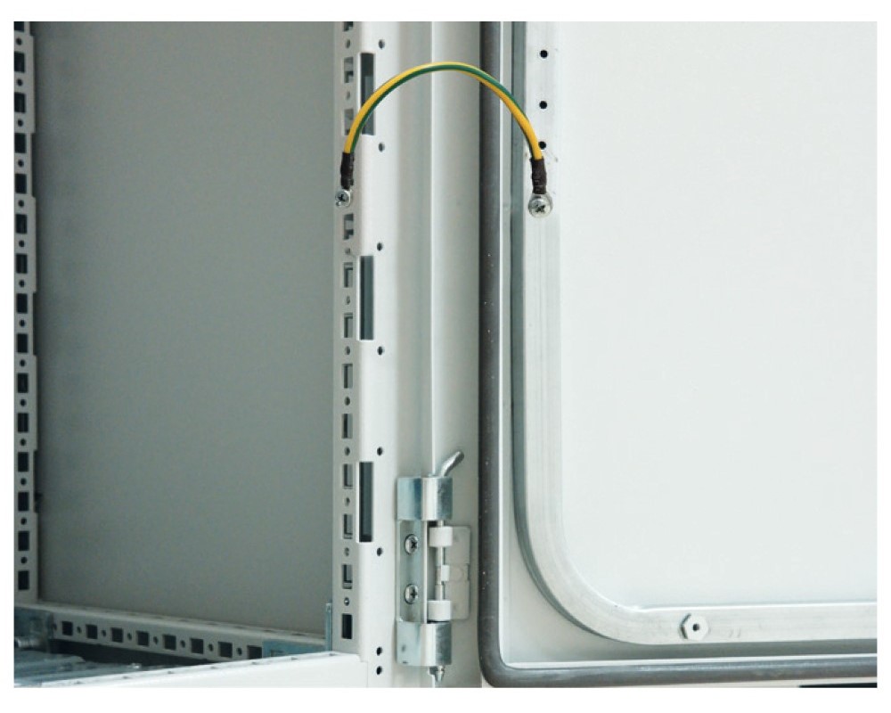
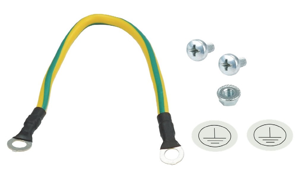
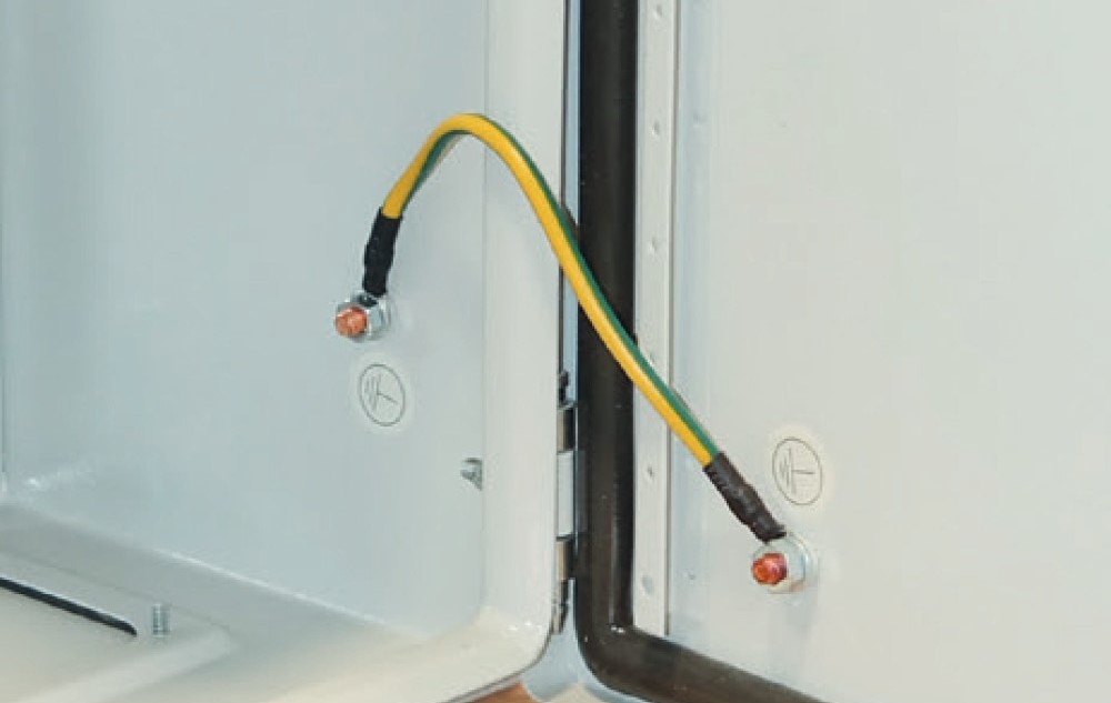
With regard to the inclusion of the door in the protection measures for “Protection in case of indirect contact” we recommend connection of a separate earth conductor to the door, when an apparatus is attached on the door and the rated operational current of the attached apparatus is higher than 16 A. The applicant must determine whether or not the integrated contacting is sufficient for the earthing system. Attention is here drawn to the regulations and standards. EAE enclosure doors are supplied with 6 mm2 cross- section earthing cable for attached apparatus rated current up to 63A.
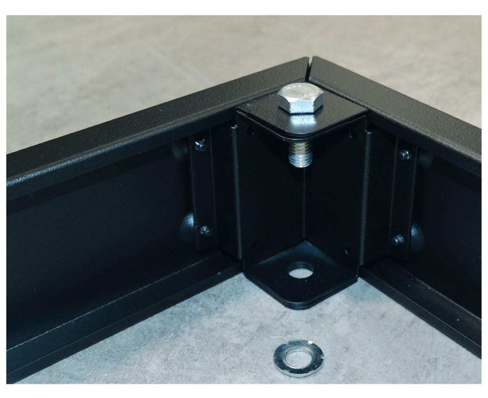
Integrated contacting
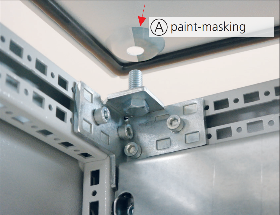
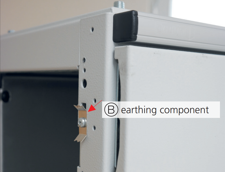
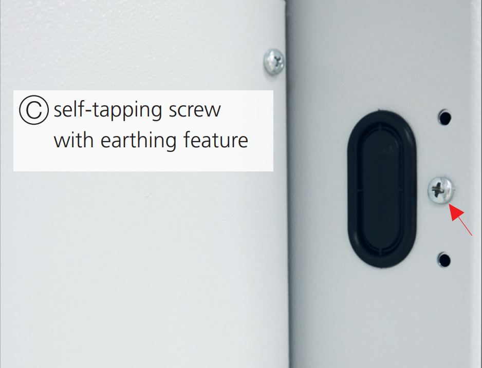
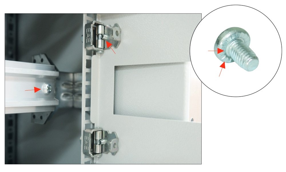
The integrated contacting system of EAE enclosures ensure a contacting connection between all elements. All elements are made of galvanized sheet steel even if they are painted for esthetical reasons.
Conducting connection of painted elements is achieved,

.jpg)
.jpg)


_shutterstock_750265378.webp)


.jpg)
.jpg)
.webp)
.jpg)
.jpg)
.png)
.jpg)
-(1)-(1).jpg)

-(1).jpg)
-(1).jpg)


.jpg)
.jpg)